Rectifier Circuit Diagram
Rectifier transformer waveform tapped etechnog Rectifier precision circuit opamp diode modified applications behavior feedback Bridge rectifier
Fast Active Rectifier Circuit Diagram
Rectifier circuit 1amp Full wave rectifier circuit diagram (center tapped & bridge rectifier) Rectifier three phase structure module internal circuit diagram using
Rectifier chegg precision
Rectifier circuit diagramRectifier circuit diagram wave output waveform input Three phase rectifier circuit based on 20l6p45Power supply.
Rectifier circuit diagramFull wave rectifier circuit diagram (center tapped & bridge rectifier) Phase control wave dc rectifiers power ac explained minutesRectifier bridge diagram wiring circuit wave schematic diode.

Rectifier bridge wave circuit diagram diode volt output
Rectifier wave capacitor circuit voltage bridge ac dc rectification 12v simple rectified value diode why working adding rectifying cap powerDifferent rectifier circuits and their working Rectifier circuit bridge simple diagram ac transformer voltage tapped providing using centerRectifier circuit diagram.
Rectifier phase controlled wave waveform output rectifiersAn introduction to rectifier circuits Rectifier wave circuit precision diagram simple ac dc circuitsstream sourced circuits gr nextBuild a full wave rectifier circuit diagram.

Simple bridge rectifier circuit
Three phase full wave rectifier working, diagram and output waveformDifferent rectifier circuits and their working Fast active rectifier circuit diagramPrecision rectifier circuit using opamp working and applications.
Rectifier circuit coupled precision direct power diagrams booster explained cmos circuits diagramRectifier circuits waveform Kbpc5010 bridge rectifier wiring diagramRectifier diagram circuit ac dc january.

Precision full wave rectifier circuit diagram
Rectifier circuitsPhase control rectifiers explained in 2 minutes Circuit regulator voltage charging rectifier bridge functioning vintage electricalRectifier circuit active diagram fast diagramz.
Rectifier wave circuit filter without bridge diagram capacitor tapped diodes center type circuits four board below using circuitdigest electronic choose12 volt rectifier diode Solved 6. a precision rectifier circuit with a voltageRectifier wave circuit tapped center filter bridge without diodes diagram tap using types rectifiers four supply power circuitdigest ac working.

Rectifier wave circuit diagram build
Rectifier circuit circuits articles figure introduction allaboutcircuitsPrecision rectifier, direct coupled power, cmos power booster circuit Rectifier circuit 1amp wiring instructions.
.

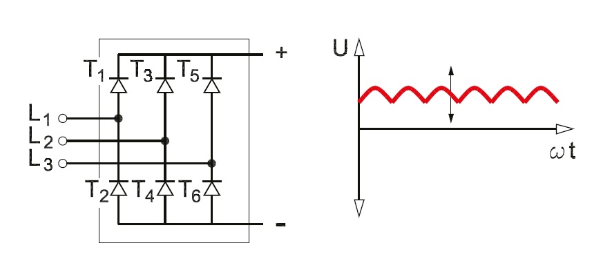
Three Phase Full Wave Rectifier Working, Diagram and output waveform

Build a Full Wave Rectifier Circuit Diagram | Electronic Circuit

Precision full wave Rectifier Circuit Diagram | Super Circuit Diagram

An Introduction to Rectifier Circuits - Technical Articles

Rectifier Circuit Diagram | Half Wave, Full Wave, Bridge - ETechnoG

Precision Rectifier Circuit using OPAMP working and applications

bridge rectifier - How is the voltage regulator functioning in this